This embedded automatic timed plant feeder system can regularly feed water to your plants for a specified amount of water and also be used as an alarm clock. The project contains the several major blocks: ATmega 323 based CPU system.
To display the time and system states, it use 24x2 LCD. A speaker is used for alarming and making sounds. While push buttons used to change the system states by user. A relay is used to control the AC of the water pump with a DC signal from the processor. For feed pattern, You can setting it up any time.
Tags: Plant feeder, Automatic, MCU project src
Showing posts with label digital. Show all posts
Showing posts with label digital. Show all posts
Automatic Plant Feeder
Arduino Digital Thermometer

This Digital Thermometer based on famous Arduino board and LM35DZ as temperature sensor. The sensor component has three pins, +5V, ground and a variable voltage output to indicate the temperature. This simple project wired the sensor output straight to the Arduino's analogue input 0. As display, it use two line LCD (a Displaytech 162B).
Tags : Temperature Measurement, Digital Thermometer, Arduino project src
Digital Clock using Classic LED 7 Segment Displays

This is a simple digital clock project using PIC16F887 and classic LED 7-Segment from HP 5082-7414 created by punkky. The displays are bright red and sun light viewable. Each clock consumes about 0.25W (50mA, 5V) when the PIC16F887 operates at 250kHz (display refresh rate is about 61Hz).
Tag: digital clock, 7 segment display, PIC project src
PIC16F84 based Hexapod Robot

This Hexapod Robot created by Mike Smyth. It uses 12 R/C servos for actuators. The 6 that raise and lower the legs are Hobbico CS-72 1/4 scale and the 6 that move the legs forward and backward are several brands of standard 1/10 scale servos (all are similar the Futaba S3003). The total robot weight is a little over 5lbs and the payload capacity is around 5lbs additional. The vertical travel of the legs is 1 7/8". Overall length and width is 13" X 11". When crouching, it's 5.5" tall. When standing up there is 3.5" of ground clearance under the body.
There are actually two PIC16F84's on the hexapod. The main processor contains all of the walking code and generates positioning pulses for all 12 servos. Twelve of the 13 I/O lines are used for switch inputs - one on the bottom of each foot and a contact sensor in the front of each leg. The servo pulses are output sequentially on the last I/O line. All the second processor does is de-multiplex the pulses from the main processor and send them to the appropriate servo
tag : Robotic, PIC16F84 Project, Electronic Design, Microcontroller Project (src)
Ethernet Interface for LED Matrix Display
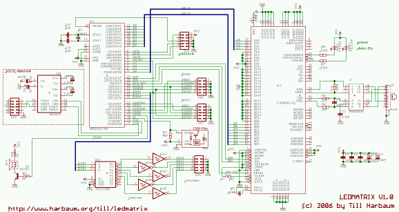
LEDMATRIX are 16x16 LED matrix units with a green and a red LED per pixel allowing each pixel to be switched to either green, red, amber or off. The goal of this LEDMATRIX project was to build a 80x32 pixel display by arranging the displays in two rows with 5 displays each giving a total of 16*16*2*2*5 = 5120 LEDs to be controlled individually.
This displays come with interated controllers and the data can be shifted into a single display using as few as 6 digital signals. By multiplexing some of the select signals all 10 displays can be controlled with a total of ten wires. Using a cheap ATmega32 microcontroller all ten displays can easily be controlled and updated in real time.This kind of display is usually controlled via RS232. This has the disadvantage of being very slow and the display data is limited to simple text messages only with the microcontroller of the display doing the actual text drawing. Instead of doing it the same way i decided to use an ethernet interface for the LEDMATRIX display. Even the most simple ethernet interface i am using is fast enough to transfer graphics data in realtime from a PC to the display allowing to update the entire screen 50 times a second. The ethernet support of LEDMATRIX is based on the cirrus logic cs8900 chip which is e.g. supported by the free Procyon AVRlib which has been used for this project.
Download : Schematic, Source Code
Tag : LED Matrix Display, Ethernet Interface, AVR Project (src)
AVR Project : SPI2CF - WLan For AVR

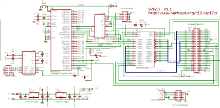
Till Harbaum has build a WLAN system, SPI2CF, which is small, simple and cheap. Using SPI2CF WLAN System you can leave much of the AVR functionality for other use and allowing fast and reliable WLAN data transfers. The final design was based on a prism chipset based compact flash WLAN card which is connected to the AVR CPU using a programmable logic chip (CPLD) made by Xilinx. Since the CF card is attached to the AVR using the SPI interface the entire system is named the SPI2CF project. You can get the complete compact flash specification from the Compact Flash Association.
The pros and cons of this solution presented here are:
Pros:
Cons:
- Requires the ability to flash a CPLD
- Uses outdated WLAN hardware
Download : schematic, verilog source code, uip port
tag : AVR, Project, WLAN, Data Transfer, Wireless Project, Microcontroller Design (src)
Read More
AVR 1-Key-Keyboard Project

This simple microcontroller project build to create a keyboard hack that is smaller and cheaper and better reproducible than what one would get when hacking a keyboard circuit. a perfect solution for when you only want to use one switch in your prototype. The project utilize ATTiny45 as main controller.
This 1-Key-Keyboard Project can be plugged into any computer and will be recognised as a standard USB keyboard. When closing the switch, the keystroke ‘]’ will be sent. When opening the switch, the keystoke ‘[’ will be sent.
Download : Source Code and schematic
related search : AVR microcontroller project, Simple Keyboard project, USB Interfacing (src)
The Ethernet Shield For Arduino

Here is an ethernet shield for Arduino. This module gives Arduino the ability to open connections to other Internet hosts or behave like a server, for example a simple web server. The design uses the w5100 chip from WizNet that implements the whole IP stack in itself providing up to 4 sockets simultaneously.
Download : Documentation and guide
related search : Arduino project, ethernet shield, electroonic project (src)
AVR General Purpose Infrared Remote Control Receiver with RS232 Output

This Infrared Remote Control Receiver can receive signals transmitted by an infrared remote control that uses the NEC protocol, or similar, with 32 bits of data. The received signal is converted to ASCII and sent on the RS232 protocol 19200bps, no parity, 8 data bits, 1 stop bit. The power is drawn directly from the serial port of your PC, as long as you activate the RTS and DTR lines, to test the circuit you can use the HyperTerminal program standard on Windows.
Download : Source Code and schematic
related search : AVR microcontroller project, Infrared Remote Control Receiver (src)
AVR Clock Output on Oscilloscope

Usually we see Digital clock on LCD or 7 segmen. But, this AVR Digital Clock which is designed by Ficara Emilio displayed on Oscilloscope. The project use ATtiny 2313 as the main controller. What an interesting microcontroller project. 
Download : Source code and schematic
related search : AVR microcntroller project, Digital Clock Circuit, Oscilloscope as Display (src)
AVR Based Direct Digital Synthesis

Sometimes you need signal generator for your electronic project. You could build your own Direct Digital Synthesis based on microcontroller. It uses AVR ATtiny 2313 as the main microprocessor. This project design by jesper.
What you get from this DDS? This circuit can generate Sinewave, Sawtooth, Trangle and Sqare-waves ranging from 0.07 Hz to about 200-300 kHz in 0.07 Hz steps (depending on microcontroller crystal).
The circuit contain Just 4 major parts. A voltage regulator/switch, a RS232 interface chip, the 2313 and the R2R resistor network. The R2R network that connected to PORTB ( AT tiny 2313 ) making a simple D/A converter and makes it possible to output 256 voltage levels. Neither the resistor network or port drivers of the 2313 is of perfect linearity, but it works pretty well anyway. But you'll probably need a buffer stage as the output impedance is rather high (tens of kOhms in my case). The MAX603 handles the voltage regulation as well as the powerup/shutdown function, and is controlled by the DTR signal on the serial interface. So when you shut down the control program on the PC, the miniDDS will be shutdown, saving battery.
Download : Schematic, ASM code, Windows Control Program
related search : AVR project, Direct Digital Synthesis, Microcntroller Signal Generator (src)
Burning the Bootloader without external AVR-Writer

When we burn the bootloader of Arduino Diecimila, we connected external AVR-Writer to ICSP of Diecimila. But Kimio found the method to burn the bootloader by Diecimila itself without external AVR-writer. It is able to do by FT232RL BitBang Mode AVR-Writer software. And, this method is usable in Arduino NG and Arduino Duemilanove too.
tags : Arduino Diecimila, AVR, Digital Electronic (src)
MAX3420 - USB Peripheral Controller
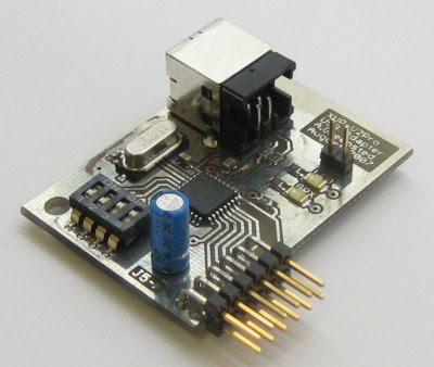
The MAX3420 provides a very simple approach to adding a USB interface to a circuit. It uses a SPI bus to connect to your system. It does require a reasonable amount of configuration and control, so you'll need to connect it to some form of microprocessor/microcontroller.
Download PCB and Circuit in Eagle
related search : Digital Electronic Project, USB Controller (src)
DS1820 and PIC based Thermometer

The project will show you how to build Digital Thermometer based on PIC 16F84A and DS1820 as the censor
Download : schematic and source code
related search : PIC microcontroller project, Digital Thermometer, DS1820, Electronic Circuit (src)
PIC-Based Temperature Alarm

Another PIC microcontroller project by professor mark. This is a simple temperature alarm which uses a PIC16C84 microcontroller and a 2-line LCD display. The alarm displays current temperature in both Celsius and Fahrenheit degrees and features a 3-key keypad which allows the user to set independent high and low termperature alarm points. The alarm also records the minimum and maximum temperatures encountered.
Related search : PIC microcontroller project, Temperature Alarm Circuit, Digital Electronic Project (src)
PIC Based RS232 - Infra Red Interface

This project is a Microchip PIC microcontroller with an RS232 serial interface on one side and an Infra-Red receive and transmit interface on the other. All mention of RS232 on this page actually refers to RS232 waveforms operating at 5V TTL levels not +/-12V levels which would destroy the PIC device. An appropriate converter between the two must be used.
By sending commands on the RS232 interface it is possible to receive or transmit a sequence of bits modulated as a series of on/off states in a 38 kHz infra-red carrier signal. Infra-Red remote controls use a carrier signal (typically around 38 kHz) so that there is no confusion with sunlight etc. The carrier is turned on and off to represent the bit sequences at a lower rate, for example 500 Hz).
Download : Schematic
related search : Microcontroller Circuit Project, PIC, RS 232, Infrred, Interface (src)
USB 8 bit Interface Board

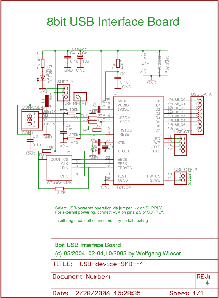
This is a USB (universal serial bus) interface board which can be used to connect 8 (parallel) data lines to the USB. The interface comes with a small internal FIFO (384 byte Tx, 128 bytes Rx) and 4 handshake lines which make it suitable for interfacing microcontroller designs to the USB.
It can, also be used as simple 8bit IO when the so-called "bitbang mode" is enabled. Note. however, that in this mode, the bits will not come out in a constant bitrate but in chunks of 64 bytes with specified baud rate followed by a delay.
Download : schematic, source code 1, and source code 2
related search : Electronic Circuit Project, USB Board, Interfaceing (src)
Microcontroller based Photoplotter

A photoplotter is a printing device that exposes light to a photo sensitive film to produce output. The film is then developed like traditional photos to get the result. There are 2 types of photoplotter, vector type and raster type. Vector plotters move the exposure light anywhere in 2D space to create the image. Need a line from point A to B? No problem, just move from A to B. These are similar to old style pen plotters. Raster plotters, are more like a dot matrix printer, sending out one line of dots, then moving to the next to create an image.
related search : Elelctronic circuit, Photo plotter, Microcontroller project (src)
Electronic Project : Computer Controlled Battery Manager

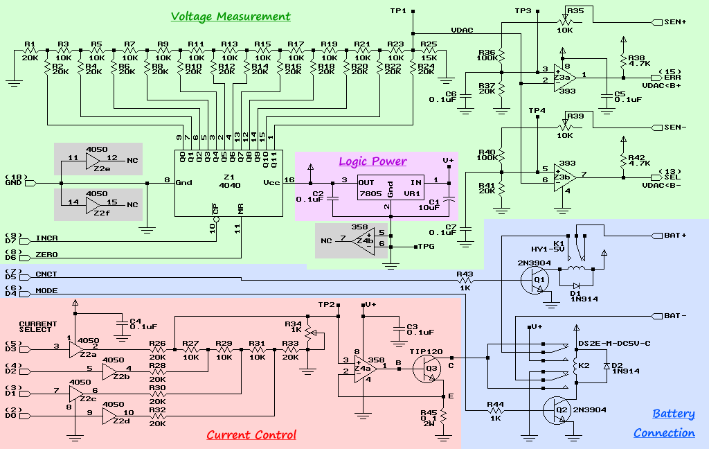
BattMan II is a computer controlled battery manager, intended for typical rechargeable batteries used by R/C and electronics hobbyists, as well as various consumer product batteries.
BattMan II has the following capabilities:
Download schematic and software
Electronic Circuit Project, Battery manager (src)
Electronic Project : Servo Tester 2
Make sure you have read the license conditions, and that you agree with them, before downloading any files. Hardware Schematic page 1 Schematic page 2 Schematic page 3 Board (Eagle format) Software Program file. Version 1.00 Source in AVR assembler. Version 1.00 Documentation User manual One-page menu overview
If you want to check your Servo, i think this electronic project is suitable for you. The project use microcontroller AVR AT mega 16 as main processor. The Servo Tester 2 is hardware and software that, basically, makes a pulse width signal between 1 and 2 ms. This is the signal used to control common R/C servos. This one has some advanced features, not usually found on servo testers. This project created by ejberg
Feature list:
Download :
Servo Tester, electronic circuit project, Tachometer (src)
Subscribe to:
Posts (Atom)
Free Magazines
Download this guide to learn and understanding everything you need to know about the Raspberry Pi computer, system specs, the software it runs and the amazing project based on this little PC.

PEI is the leading magazine for the global electric power generation and transmission industry. PEI provides articles on new technologies and installations and analysis.
Subscribe Fof Free!

EDN magazine provides how-to solutions for design engineers in the electronics industry. Engineers turn to EDN because they know they will always find valuable design techniques that they can use to do their jobs faster.
Subscribe Fof Free!
More Free Engineering Magazine

Headlines