Soldering Iron is a must have tool for electronic engineer or Hobbyist. Choosing good soldering iron can make your electronic project designing process faster and have good result in circuit connection.
The Weller WLC100 Soldering Station includes everything you need to start using solder to join metals and create efficient, electrical connections. Designed with the hobbyist and the do-it-yourself enthusiast in mind, this kit features a high-quality, lightweight pencil iron with variable power control, a cushioned foam grip with a replaceable heating element, and a safety guard iron holder. And it’s from Weller, the world leader in soldering since 1945.
Showing posts with label electronic. Show all posts
Showing posts with label electronic. Show all posts
Electronic Tools : Weller WLC100 Soldering Station

AVR Based Direct Digital Synthesis

Sometimes you need signal generator for your electronic project. You could build your own Direct Digital Synthesis based on microcontroller. It uses AVR ATtiny 2313 as the main microprocessor. This project design by jesper.
What you get from this DDS? This circuit can generate Sinewave, Sawtooth, Trangle and Sqare-waves ranging from 0.07 Hz to about 200-300 kHz in 0.07 Hz steps (depending on microcontroller crystal).
The circuit contain Just 4 major parts. A voltage regulator/switch, a RS232 interface chip, the 2313 and the R2R resistor network. The R2R network that connected to PORTB ( AT tiny 2313 ) making a simple D/A converter and makes it possible to output 256 voltage levels. Neither the resistor network or port drivers of the 2313 is of perfect linearity, but it works pretty well anyway. But you'll probably need a buffer stage as the output impedance is rather high (tens of kOhms in my case). The MAX603 handles the voltage regulation as well as the powerup/shutdown function, and is controlled by the DTR signal on the serial interface. So when you shut down the control program on the PC, the miniDDS will be shutdown, saving battery.
Download : Schematic, ASM code, Windows Control Program
related search : AVR project, Direct Digital Synthesis, Microcntroller Signal Generator (src)
Burning the Bootloader without external AVR-Writer

When we burn the bootloader of Arduino Diecimila, we connected external AVR-Writer to ICSP of Diecimila. But Kimio found the method to burn the bootloader by Diecimila itself without external AVR-writer. It is able to do by FT232RL BitBang Mode AVR-Writer software. And, this method is usable in Arduino NG and Arduino Duemilanove too.
tags : Arduino Diecimila, AVR, Digital Electronic (src)
LM35 and TL431 Automatic Temperature Control
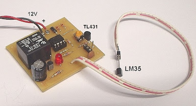
This is an electronic circuit that can be used as automatic temperature control aapplication. The circuit switches a miniature relay ON or OFF according to the temperature detected by the one-chip temperature sensor LM35. When the LM35 detects a temperature higher than the preset level (set by VR1), the relay is actuated. When the temperature falls below the preset temperature, relay is de-energized. The circuit can be powered by any AC or DC 12V supply or battery (100mA min.)
Download : schematic, layout and PCB (pdf)
related search : Electronic circuit project, automatic application, temperauter controller, LM 35 (src)
Infrared Thermometer Module

If you want to build non Contact Thermometer, you can try to use MLX90614. It will reduce your electronic project complexity. Outputs of this module is continuous data flow with an active alarm running in the background, 16-bit digital temperature output data that ranging from -70 °C to 380 °C and Serial data (Auto-baud detection (2400, 4800, 9600, 19.2K, 38.4K)) for microcontroller-to-MLX90614 communications.The MLX90614 Infrared Thermometer Module is an intelligent non-contact temperature sensor with a single pin serial interface for connection to most microcontrollers. The MLX90614 sensor is designed for non-contact temperature measurements of objects placed within the sensor’s cone of detection. The sensor is comprised of an integrated ASIC and infrared sensitive thermopile detector.
tags: Electonic Module, Infrared Thermometer (src)
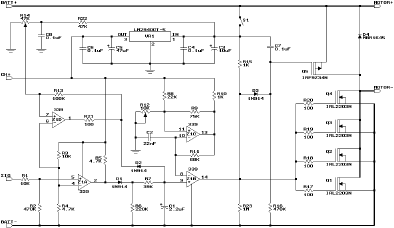
Miniature High-Rate ESC Circuit

This electronic speed control (ESC) is an analog one, using off-the-shelf components. There are no microprocessors (which would require specialized equipment to program), and no surface-mount parts. It's not as small or as light as many commercially available ESCs, but it's smaller than many other do-it-yourself designs. It's also versatile, in that it can be built for many applications, ranging from small Speed 400 sport planes to "hot liner" sailplanes.
Download : schematic
tags : Electronic Analog Project, electronic speed control (src)
Buck Mode Switching Regulator

This circuit is suitable for a variety of uses. If you have a solar powered 12 Volt lead-acid battery power source, the circuit can be used to efficiently power lower voltage devices. It can be used to provide power to devices that normally use a set of small batteries for power. Common voltages such as 1.5V, 3V, 4.5V, 6V, 7.5V, and 9V can be produced by this circuit. The circuit has been used to power small fans, portable radios, a miniature TV, and more.
Another application for this circuit is as a linear current booster (LCB). Common LCB uses include running motors and other devices directly from a solar panel with no battery. In the LCB mode of operation, it is possible to use the circuit to change a low current solar panel input to a higher current (but lower voltage) output.
Download : schematic
tags : Electronic Analog Project, Buck Switching Regulator, linear current booster (src)
Project : Radio Controlled Clock with USB

Most widely spread DCF77 radio-controlled clock receiver are connected computer via the serial port but this electronic project will show you how to make DCF77 radio clock receiver connected via USB using a small 8-pin microcontroller ATtiny45. The project programed with the smart firmware called AVRUSB and AVR-CDC. With this firmware combination, the DCF77 receiver creates a serial port and is fully compatible to old-style true-serial-port ones. No software adaption is necessary.
Download : schematic and Firmwire
tags : Microcontroller AVR Project, radio-controlled clock receiver, USB (src)
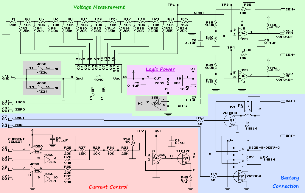
Electronic Project : Computer Controlled Battery Manager

BattMan II is a computer controlled battery manager, intended for typical rechargeable batteries used by R/C and electronics hobbyists, as well as various consumer product batteries.
BattMan II has the following capabilities:
Download schematic and software
Electronic Circuit Project, Battery manager (src)
Electronic Project : Precision Battery Discharger

This is a precision battery discharger for 8.4V 7-cell Ni-Cad or Ni-MH batteries. It's cheap, reliable discharger circuit with an easy visual indication of the battery’s state (discharging or discharged) with less than 10$ of parts. Most parts can be found around the house or taken from broken electronic equipment or purchased from Radio Shack.
The circuit as shown only works with 7-cell (8.4V) NiCd or NiMH battery packs, but with a couple additional parts it can also work with 8 cell 9.6V packs..
Download : schematic
Electronic Circuit Project, Battery Discharger, Analog circuit (src)
Electronic Project : Servo Tester 2
Make sure you have read the license conditions, and that you agree with them, before downloading any files. Hardware Schematic page 1 Schematic page 2 Schematic page 3 Board (Eagle format) Software Program file. Version 1.00 Source in AVR assembler. Version 1.00 Documentation User manual One-page menu overview
If you want to check your Servo, i think this electronic project is suitable for you. The project use microcontroller AVR AT mega 16 as main processor. The Servo Tester 2 is hardware and software that, basically, makes a pulse width signal between 1 and 2 ms. This is the signal used to control common R/C servos. This one has some advanced features, not usually found on servo testers. This project created by ejberg
Feature list:
Download :
Servo Tester, electronic circuit project, Tachometer (src)
RS485 to RS232 Converter

Converter is intended to use with PC computer to communicate with ROV using 2 wires in half duplex mode. Send/receive mode is selected by RTS signal. The converter was designed to be as simple as possible, so it has no some features that can be found in commercial grade products (e.g. galvanic separation).
Popular chip MAX232 is used to convert RS232 signals from/to TTL level. MAX485 converts TTL level signals to RS485 standard. RTS line is used to change transmission mode of MAX485. RTS signal is first converted to TTL level by MAX232 then connected to DE and RE/ pins. 2 LED are used to indicate current state of the interface.
download RS485_to_RS232_Converter_Schematic.pdf RS485_to_RS232_Converter_Elements.pdf RS485_to_RS232_Converter_BOM.pdf RS485_to_RS232_Converter_PCB.pdf
Electronic Circuit project, RS485 to RS232 converter, Digital circuit (src)
R/C Transmitter Range Tester

This project suitable for people who like with the transmitter system. It's an electronic analog project. You don't have to programming the IC to build it. The function of this electronic project is to measure the RF power being radiated from a transmitting antenna.
Among the Amateur Radio fraternity, a device such as the one described here would otherwise be known as a Field Strength Meter (FSM). Its main purpose would be to check that RF power is being radiated from a transmitting antenna. Some FSMs are tuneable across a wide range of frequencies, which allows the device to work with different transmitters and antennae - usually from HF to VHF and beyond. A difference with this unit is that it is only sensitive to those signals in the R/C section of the radio spectrum. The on-board trimmer allows you to tweak for maximum signal strength of your frequency of choice, whether it be 27MHz AM, or 40MHz FM.
In order to read the received signal strength, such a unit would ordinarily employ a mechanical analogue meter. The unit described here differs in that it uses four super-bright LEDs. The benefit of this is that it allows you to read the display from a distance - even in bright sunlight.
Download schematic(gif), PCB1, PCB2
Electronic Circuit Project, FM tranmitter, Field Strength Meter, Analog circuit (src)
Electronic Project : Simple IR (Infra Red) Receiver
by Alessio Sangalli
I guess this is the simplest IR receiver circuit i ever know. It's only use few pasive component and TSOP 1738 IR receiver that housing on Sub-D 9-pin serial box.
This circuitry allows you to control your computer with a simple remote, like the one you already use for your TV-set. It's very useful when you want to control a DVD or an mp3 player without having to stay at the keyboard. Please note that this circuit is NOT IrDA compatible and it won't help you to connect to your mobile phone or whatever IrDA device; it's only good to control your pc with a standard remote control. I use it for VDR and now my pc is a full featured set top box connected to the television, capable to digitally record and replay satellite television, DVDs and every kind of digital content (mp3, divx). There are many softwares you can install to control this ciruit; for Linux you can use Lirc and for Windows you can use either Winlirc, Girder, IR Assistant or uIRC

IR Receiver, simple electronic project, digital project link
Read More
Traffic Light Control Circuit

This electronic project based only on 74LSxx family and IC 555 as clock source. It's a digital logic circuit. To build Traffic Light Control you don't need microcontroller programming.
This page features a circuit that has twenty open collector outputs that turn on one at a time in a continuous sequential manner. The circuit make use of the 74LSxx family of TTL integrated logic devices. The circuits are designed to drive light emitting diodes or low current, low voltage incandescent lights but can also drive other loads of up to 80 milliamps.
download schematic
traffic light circuit, digital logic circuit, electronic project link
MICRF102 Based RF data logger

Telemetering is a methode to measure voltage, temperature or any other variable which long distance between censor and data processor. There are many ways to implement telemetering, one of them using wireless RF data logger. What do you need with this project is Rf transmitter, RF receiver and Data processor (PC) . Any number of these recorders transmits data packets to a central PC-based receiver. A PC program stores the information for later analysis.
The RF data logger project use small RF IC's the MICRF102 from Micrel because it's good compromize between price and complexity. The MICRF102 is a low power ASK transmitter IC. It generates UHF frequencies by PLL multiplying a crystal oscillator frequency by 32. In this case a 13,56MHz crystal provides a 433,925MHz carrier. The data recorder is controlled by a small AVR TINY45 microcontroller.
Download schematic RF transmitter (gif)
Download schematic RF receiver (gif)
[source]
USB Audio Digital to Analog Converter

I want to build high quality preamplifier with built-in DAC from SPDIF or USB for my power amplifier Leachamp. I tried to design DAC from USB with this circuit on one-sided PCB and I was successful.
Schematics is from datasheet of PCM2902. Circuit includes DAC and ADC, SPDIF output and input and HID part with 3 buttons for MUTE, VOL+ and VOL-. I used only DAC part. Other parts are not used. For high quality playback is needed to use external low-drop voltage stabiliser for DAC part. I used LP2951CM which was available at local store. Output voltage is set to about 3.7V with two resistors. Circuit board is designed regarding to good ground placement and separating of analog and digital ground. These ground are connected in one point at USB connector.
[source]
Windmeter using Microcontroller

The Windmeter is an anemometer designed to measure and record wind speed distribution from 0 to 17+ meters per second. It was designed for high reliability, ease of construction, and for a wide environmental range. Data is logged over a period of 30.46 days (1/12 of a year), and then saved for 11 months. The data can be retrieved with a laptop computer any time within the 12 months of logging. The Windmeter is self-powered by a solar pannel and battery. Calibration of the Windmeter can be done against a car's speedometer or better yet a GPS receiver. The Windmeter should cost you under $300 to make
[source]
Visual Analyzer Oscilloscope

Oscilloscope is tools for electronic designer must have. Unfortunatelly, the price for this hardware is too expesive especially for stuedent. But you can try Visual Analyzer Oscilloscope created by Sillanum Software.
Visual Analyzer is a free software oscilloscope. They describe it as "A complete professional real time software that transforms your PC into a complete set of instruments. No new hardware is necessary (you can use the Sound Card of your PC)."
Read more and download it click here
Simple Metronome Project

Daniel designs this Metronome with a few simple electronic components.The Metronome is any device that produces a regulated audible and/or visual pulse, usually used to establish a steady beat, or tempo, measured in beats-per-minute (BPM) for the performance of musical compositions. It is an invaluable practice tool for musicians that goes back hundreds of years.
Material Needed:

1. 555 IC
2. 3x 1K Ohm Resistor
3. 2x 22uF 16V Capacitor
4. 9V Battery
5. 8 Ohms Speaker
6. 250K Ohms Potentiometer
[link]
Read More
Subscribe to:
Posts (Atom)
Free Magazines
Download this guide to learn and understanding everything you need to know about the Raspberry Pi computer, system specs, the software it runs and the amazing project based on this little PC.

PEI is the leading magazine for the global electric power generation and transmission industry. PEI provides articles on new technologies and installations and analysis.
Subscribe Fof Free!

EDN magazine provides how-to solutions for design engineers in the electronics industry. Engineers turn to EDN because they know they will always find valuable design techniques that they can use to do their jobs faster.
Subscribe Fof Free!
More Free Engineering Magazine

Headlines


/Thermostat1-sch.jpg)
/thermostat1-pcb.JPG)